


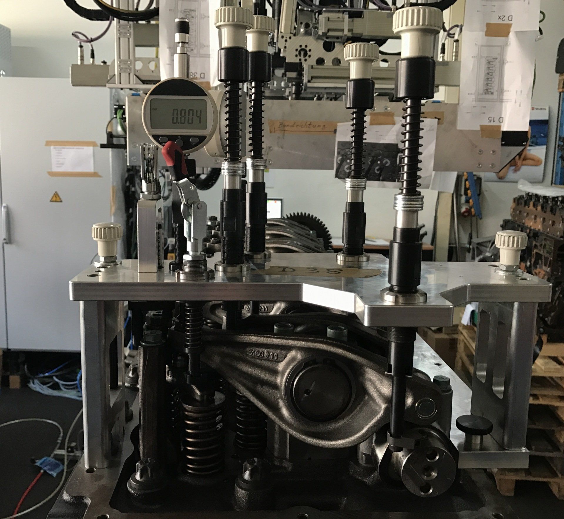
Ventilspielschrauber 2 MTU
The queen discipline - Valve play screwdrivers
And we are proud to be world market leader!
Pull the lateral forces straight
Adjusting the valve clearance - measurable and traceable - is the biggest challenge in engine mounting. Here you have a lot to do with lateral forces. The secret of our valve timing systems is to eliminate these forces in a controlled tightening process. We realize this with manual systems of semi-automatic systems fully automatic systems. In order to ensure your quality, you still need a performance measuring master for calibration. See some examples below
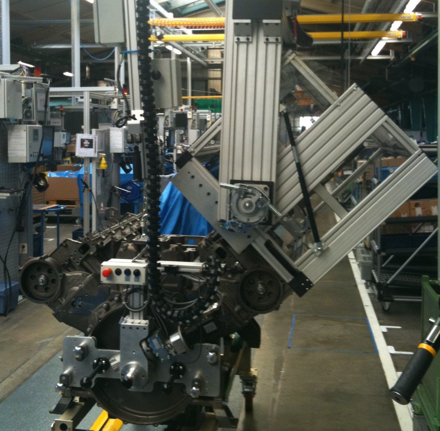
Manual valve lash adjustment Large engines 4 MW For adjustment, one setting unit is sufficient for an 18-minute cycle time. The unit must be rotatable about its own axis with V motors. Positioning on a cylinder head is done manually. The adjustment between inlet and outlet valve is automatic. The delivery of the spindle also. The X- and Y- Z and tilt axis of the entire unit are moved with EC drives. Delivery of the unit with pneumatic balancing control and up-Abfunktion with adjustable Auflagdruck.Verfahrung the Unit with electric rail drives and automatic positioning per cylinder. Monitoring of the correct support via 4 initiators as area monitoring in 2 levels. The system is clamped internally to the rocker shaft and oriented to the valves. Adjustment parameters for each cylinder separately to compensate for mechanical engine influences. Measurement of setting dimensions without turning the KW, since the games in the engine are too large. The rating of the quality of the setting depends on the comparison to manual adjustment. Monitoring the correct NW position on position query the KW turning device and optical monitoring of individual tilting hoist lstellungen. There was no access to recognizable NW positions.
Valve driver DAF
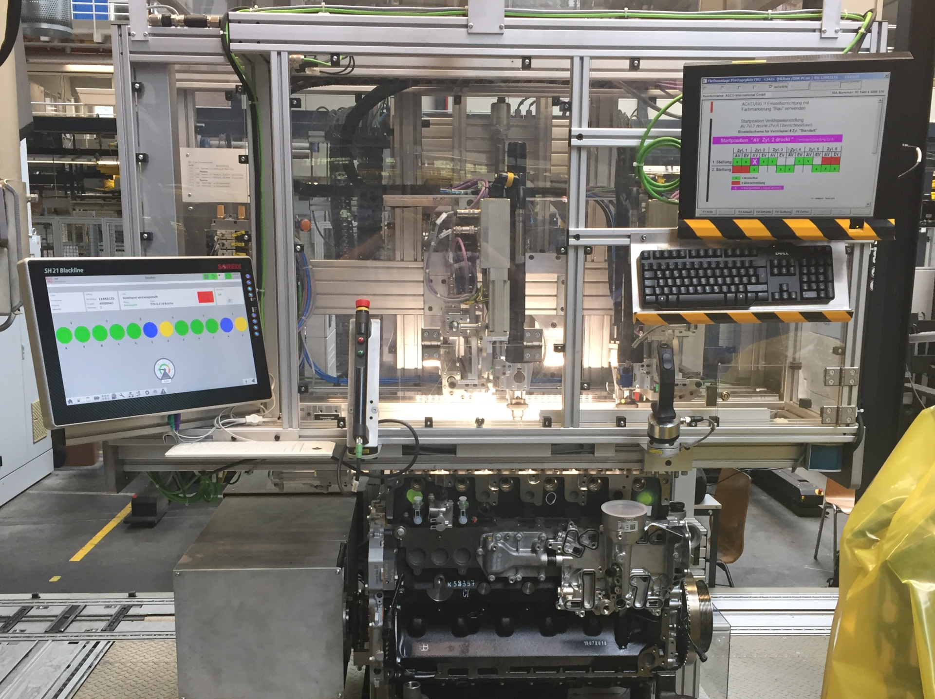
Semi-automatic valve lash adjustment Truck engines 300 KW with3 adjustment systems in parallel, because of short cycle time - Manual delivery of the unit and the turntable Response time with 12 valves to be set 105 seconds.Adjustment time with additional 6 engine brakes 150 secondsTotal cycle time depends on the manual positioning tasks.The unit is only vertical from above placed on the engineThe positioning on the engine is done manually on a previously placed glasses. X- and Y-axis are motor driven Z-axis with pneumatic balancing control and up-down function with adjustable contact pressure. Monitoring of the correct support via 3 initiators as area monitoring. Experience of the 3 adjusting spindles over XY-Z and inclination axis with EC drives. Positioning parameters for each Motor type disconnected.Setting parameter for each valve separated to compensate for mechanical engine influences.Pre-positioning Rocker arm over low-pressure cylindersQuick changeover systems due to different wrench sizes on different engines.
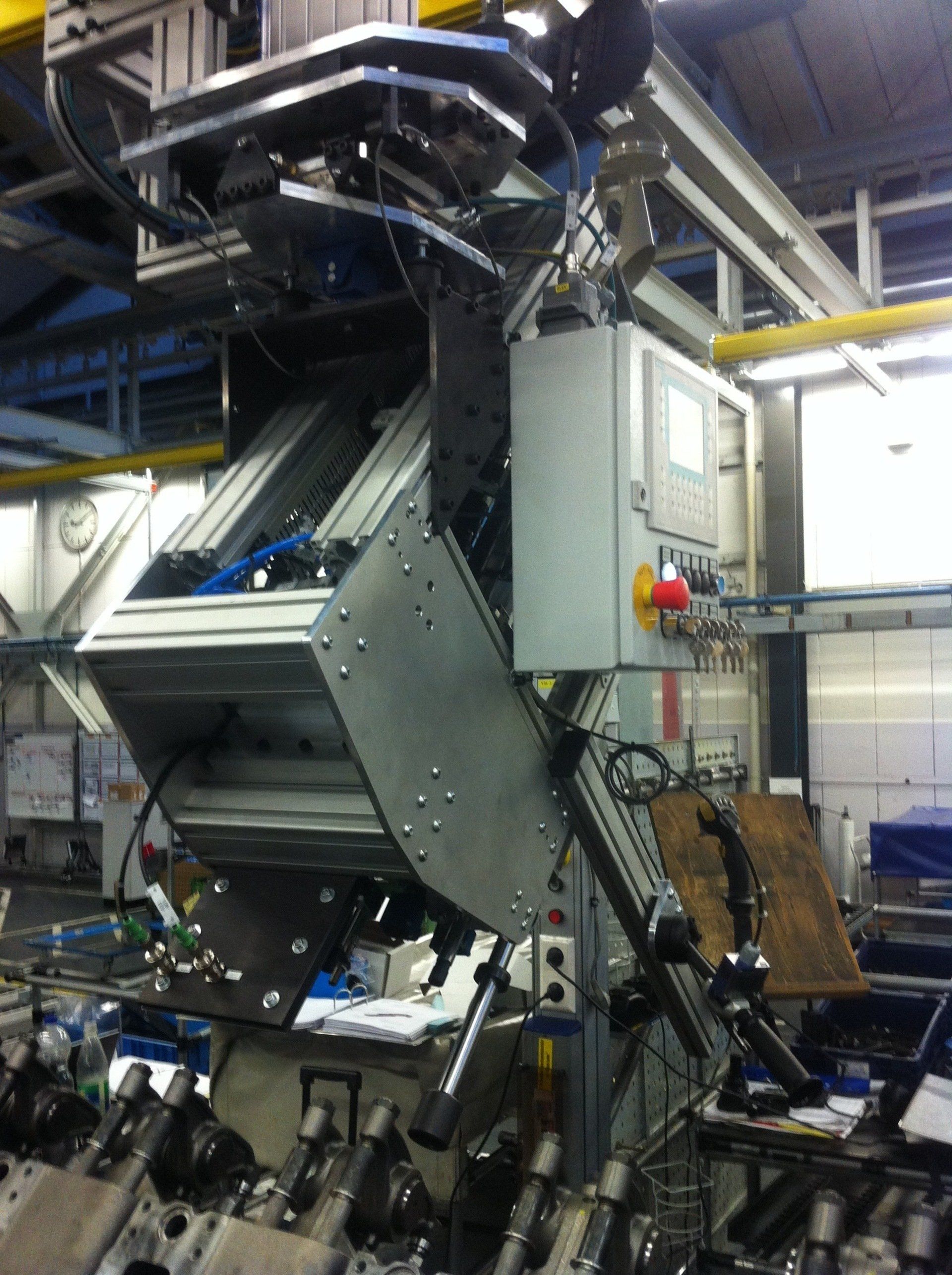
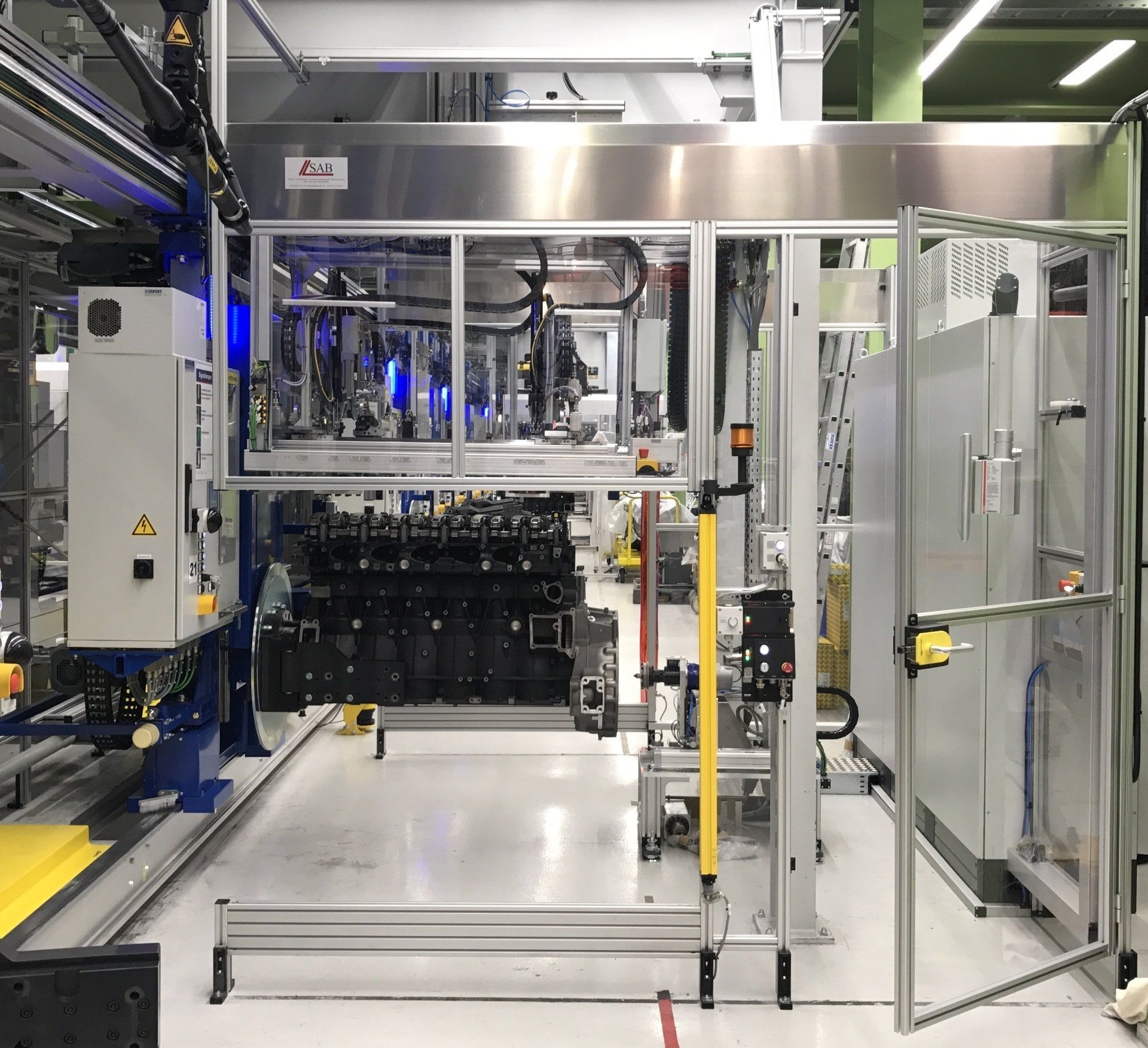
Ventilspielschrauber 1 MTU
Semi-automatic valve lash adjustment Large engines 750 KW With a cycle time of 12 minutes, one adjustment unit is sufficient. The unit can be swiveled because of the mixed operation of V and R motors. It can therefore be rotated on its own axis. Positioning on a cylinder head bank is done manually from above and via a guide bevel on the cylinder head cylinder head. Z-axis with pneumatic balancing control and up-down function with adjustable contact pressure. Monitoring of the correct overlay via 3 initiators as area monitoring. The system is clamped to the cylinder bank to allow flow operation. Experience of setting spindle via XYZ and inclination system with EC drives. Positioning parameters Separated for each type of motor.Setting parameter for each cylinder or each valve separately to compensate for mechanical motor influences by valve spring feedback.Experience of the entire unit via electric rail drives Rotary drive mounted on pneumatic compensating element for manual mounting on flywheel housing coupling to KW flange via spring mechanism. Position monitoring NW and KW with inspection of the correct position.
Valve wrench Deutz
Semi-automatic valve clearance adjustment, large engines
Valve wrench MAN
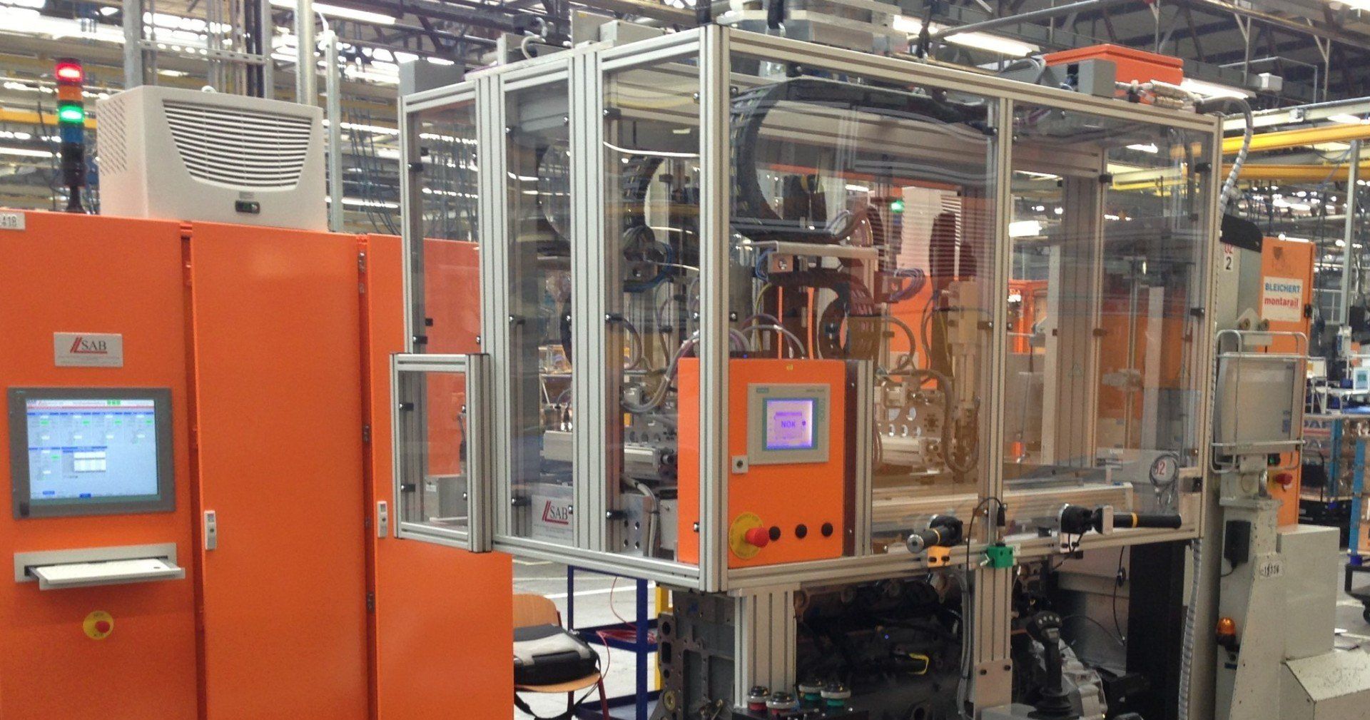
Fully automatic valve lash adjustment Truck engines 300 KW Engine is transported on AGV and drives into the plant.Versification of the coarse position in the station and correction of the position coordinates for the pre-positioningCorrection of the pre-positionCoupling of the KW turning device via crankshaft flange adapter - electric and pneumatic positioning Delivery of the whole unit pneumatically balanced with lifting Abfunction and contact force adjustment.Exact measurement of the cylinder head position in the room to 0.1 mm accuracy.Coordinate transformation for the positioning parameters, adjustment of the adjusting spindles each XY-Z and tilt axis electrically driven.Automatic course of the settings of the valves with 2 spindles for the valves and 3 th spindle for motor brake adjustmentThe Adjusting spindles are moved to the setting positions in the inclination and vertically delivered via a positioning axis. After all, adjust in the camshaft position When the valves and brakes are adjusted, the next camshaft position is automatically approached. Once all is done, the setting unit is disconnected, the turntable decoupled, and the units go home. A release is made to the AGVS
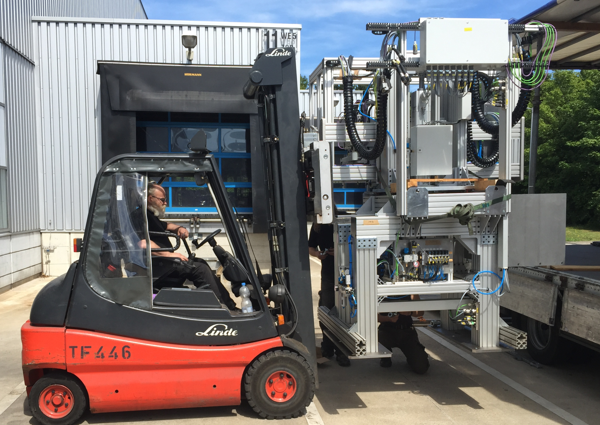
Ventilspielschrauber to go
Specifications: Here you can see our - not only technically - heavyweight. The giant sets off on the journey
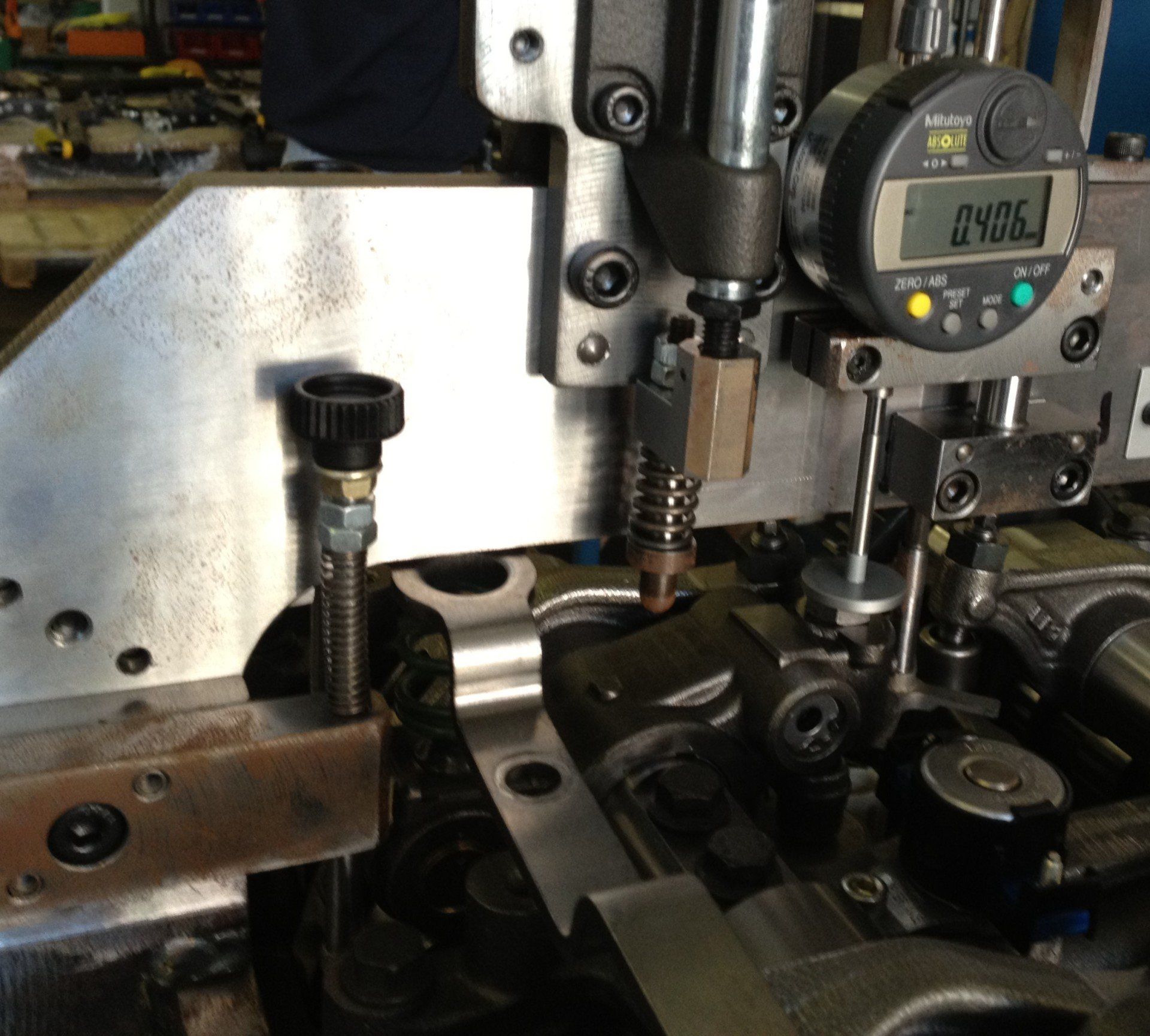
Game measuring DAF
Calibration system with digital dial gauge
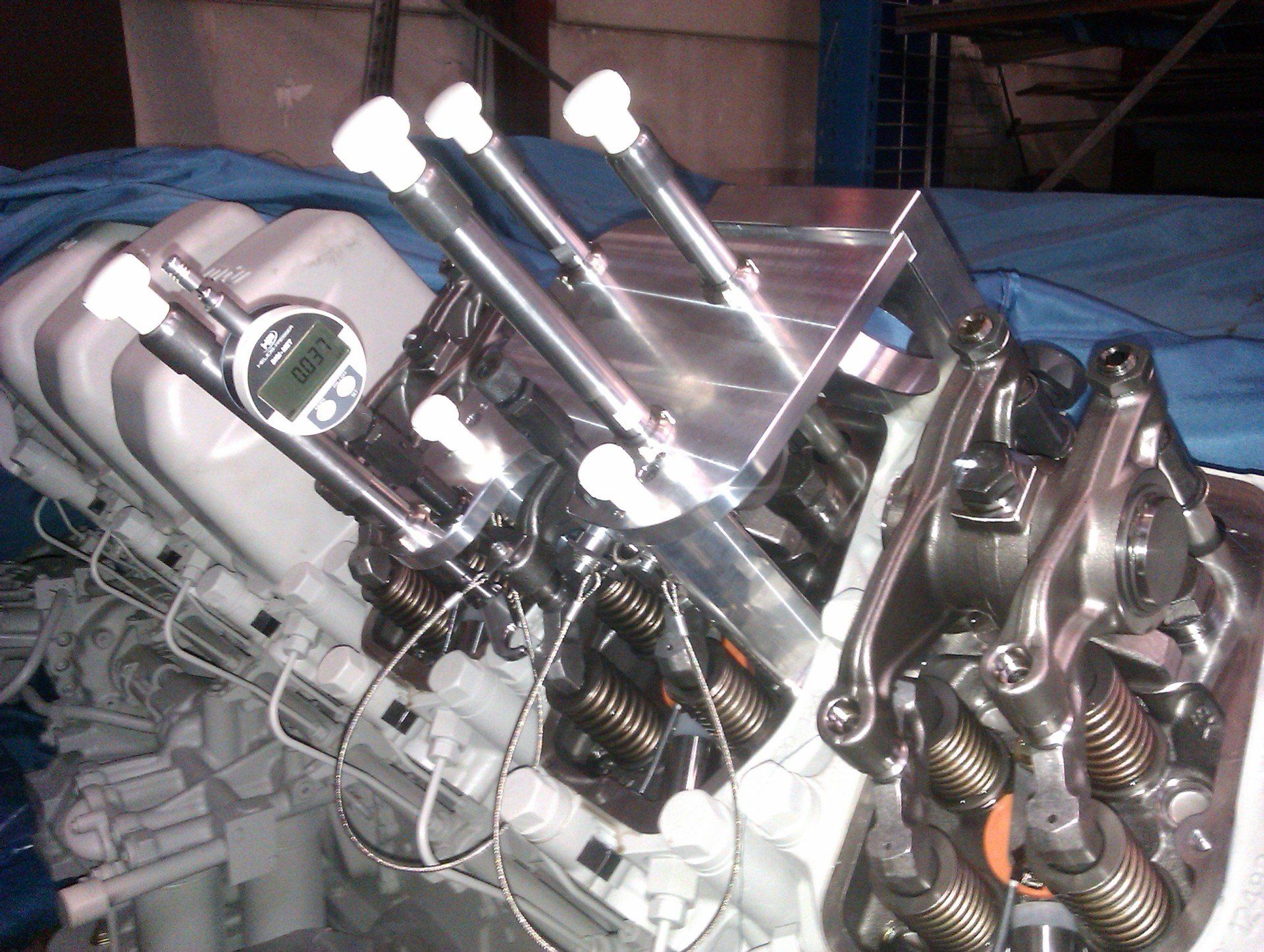
Spielmessmaster MTU
Calibration system with digital dial gauge
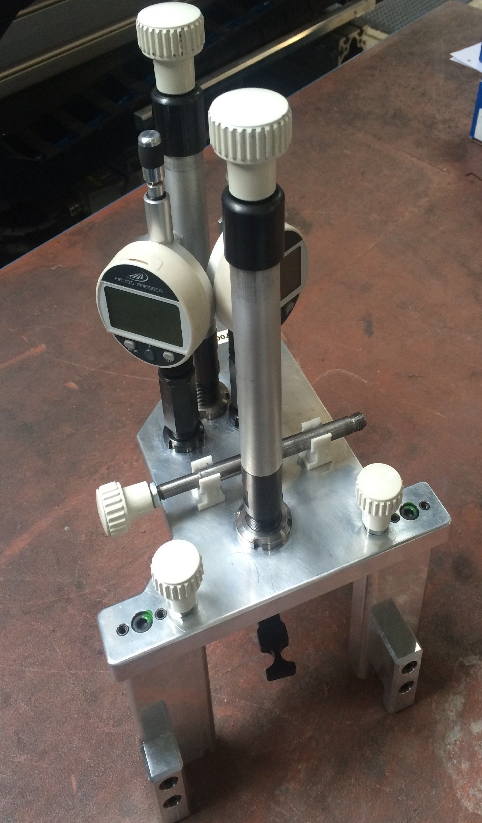
Spielmessmaster Deutz
Calibration system with two digital dial gauges
Game measuring master MAN
Calibration system with digital dial gauge